20
68
Spécial « Congrès Acoustics 2012 »
Noise source identi cation techniques : simple to advanced applications
Beamforming
Beamforming has become a popular technique for noise
source identification for exterior vehicle noise (cars, trains
and aeroplanes) and also in wind tunnels on both models
and full sized vehicles.
Beamforming is somewhat similar to a camera in that
an array of microphones in combination with beamfor-
ming calculations behaves as a lens. The technique is
based on a delay and sum principle, where an array
of microphones is used to capture the sound field [6].
The array itself is usually plane although a funnel shaped
array may be used in order to suppress background
noise arriving from the rear of the array. The signals
are then connected to a signal processor to determine
the directional characteristics of the incoming sound.
The beamforming array is most sensitive to sound arriving
from a focus direction. This region is known as the main
lobe. Sound from other directions will also be detected
to a certain degree; these regions are known as the side
lobes. A good array design is characterized by having
a large difference in the sound levels measured at the
mainlobe and at the highest side lobes. The greater this
difference, (known as the Maximum Sidelobe Level) the
better the array is at reducing spurious peaks known as
ghost images. Arrays with a regular grid of micropho-
nes are notorious in producing ghost images when the
spacing between the microphones is larger than half a
wavelength. Ideally, the array should have the micro-
phones randomly distributed but this is not feasible for
a practical system. A useful compromise is to build an
array with identical segments, each segment containing
a random distribution of microphones in order to opti-
mize the performance of the beamformer over a wide
frequency range.
Refined beamforming
Delay and sum beamforming has a spatial resolution
of about a wavelength. However if the source under
test can be modelled by a finite number of non-corre-
lated point sources, a refined beamforming techni-
que based on deconvolution algorithms such as NNLS
(Non-negative least squares) and DAMAS (Deconvolution
Approach for Mapping Acoustic Sources) [7] can be
used to improve the spatial resolution by a factor of
typically three to ten.
Fig. 5: Sound Intensity maps based on beamforming
measurements in a wind tunnel. Left: delay and sum
method. Right: Refined beamforming method
Cartes d’intensités sonores basées que les mesures
de faisceaux dans une soufflerie. A gauche : méthodes
de retard et de sommation. A droite :
méthode pure des faisceaux
Moving source beamforming
The moving source beamforming method can be employed
when the source under test is in motion, such as a vehicle
or train pass-by, an aircraft fly-over or a wind turbine [8].
In these situations, it is necessary to take into account the
Doppler effect, turbulence effects and industry specific
representation of the results. Where large ground based
areas are employed, for example for aircraft fly-over, the
correlation length between the microphones needs to be
considered; a frequency dependent shading is useful in
these cases to utilize the entire array area at low frequen-
cies and a reduced central area at high frequencies.
For open sources such as lorries and trucks, special line
displays and sliced cubes have been employed to locate
sources on the vehicles. Moving source beamforming
measurements have been successfully added to standar-
dised pass-by measurements on test tracks, thus enabling
type testing and research and development work to be
run in parallel.
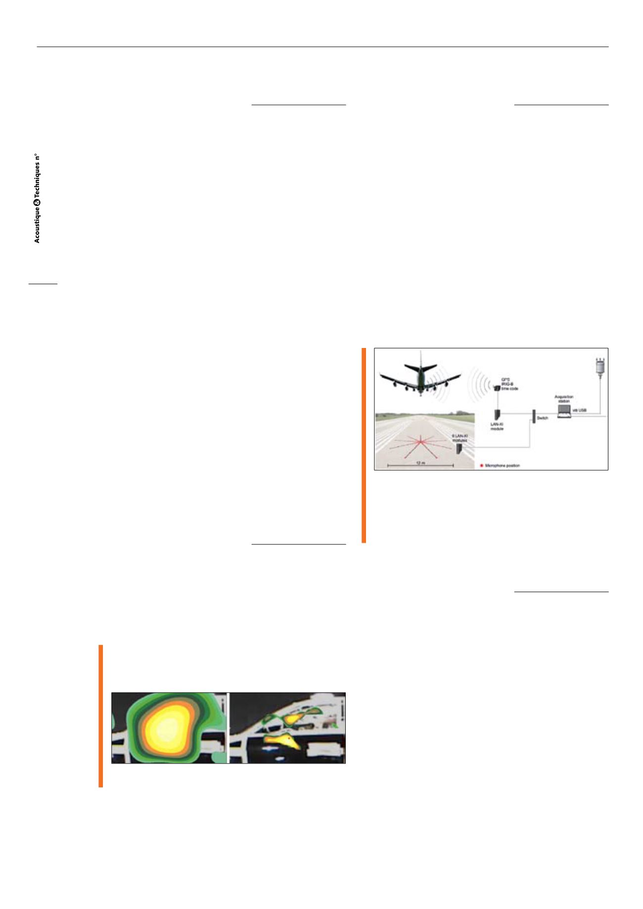
Fig. 6 : Typical system for measurement and data acquisition for
Noise Source Identification during flyover of passenger
aircraft using Moving Source Beamforming
Système caractéristique d’acquisition des mesures et
des données pour NSI lors de l’atterrissage d’un avion
de ligne en utilisant la méthode des faisceaux pour
sources mouvantes
Spherical beamforming
Spherical beamforming is the extension of planar beam-
forming to spherical arrays. Thanks to the array shape,
no preferential directions are considered; therefore we
are able to look at all directions around the sphere. This
makes this type of array eminently suitable for enclosu-
res, such as rooms or cabins. Obviously, it can be applied
to free-field conditions as well.
Different types of techniques are applied to process the
signals on the microphones. One typical and robust tech-
nique is based on spherical harmonics functions; usually
referred to as called Spherical Harmonics Beamforming
[9]. The sound field is sampled by the microphones on the
sphere, and decomposed into spherical harmonics functions
of different orders. Based on this decomposition, a direc-
tional function can be derived, to estimate the contribution
from a specific direction. Applying this process to all direc-
tions around the sphere provides the acoustic map.
As for (planar) beamforming technique, limitations occur
in terms of resolution and dynamic range. The resolution
is mainly governed by the sphere’s radius: the larger the
sphere, the better is the resolution for a given frequency.


