Version HTML de base


47
Once the rachis model is generated, dynamic analyses are
carried out on the model through the finite elements Ansys
Workbench (Ansys© workbench). The mechanical proper-
ties of the various elements (cortical shell, cancellous bone,
posterior elements and cartilaginous endplates, intervertebral
disc) forming the vertebral body were deduced from literature
[38-40]. The materials properties are given in Table 2.
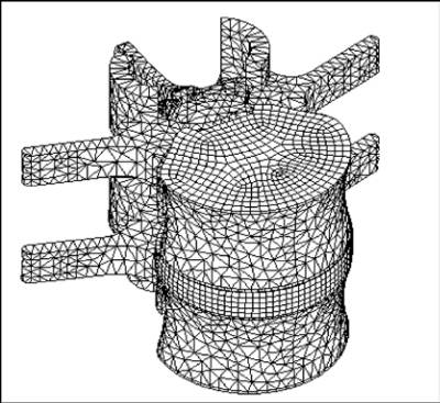
Model of the L4-L5 is composed of 12 bodies (annulus,
nucleus, endplate, cortical shell and spongy bone) and 18
zones of contacts are defined between the bodies. The mesh-
ing parameters are same as of the rachis model. However
the annulus matrix of the intervertebral disc was modelled
as a non-linear hyperelastic material. The total number of
elements is about 50292 and the number of nodes is 112377.
The meshing of the L4-L5 is shown in Figure 2.
Fig. 2 : FE models of L4–L5
Once the L4-L5 model is generated, fatigue analyses
are carried out on the model through the finite elements
Ansys Workbench (Ansys© workbench). For the dynamic
analysis of the lumbar rachis, a distributed mass of about
57% the body weight was applied to the upper face of
the rachis [19, 38] for modelling the upper body. Within
the framework of fatigue analysis, the lower face was
subjected to various vertical accelerations ranging from
0.315 ms-2 to 3.15 ms-2. These acceleration amplitudes
were chosen in the range that can be met in industry in
order to represent a range from very low risk to high risk.
These values are in accordance with the values defined in
ISO 2631-1 [41] curves for describing the vertical accel-
eration exposure limits based on frequency and duration.
In order to simulate the effects of mechanical shock [42]
encountered on rough roads, the fatigue analysis was
also conducted by inputting very high levels of seat accel-
eration (10 to 40 ms-2). For the fatigue analysis of the
L4-L5 segment, a force was applied to the upper face
of the units. The lower face was fixed in all directions.
Fatigue behaviour
Fatigue behaviour of the cortical bone
Extensive research on fatigue fracture of cortical bones has
been performed using standardized test pieces machined
from specimens of cortical bone. The main objective of
these experiments was to obtain basic information on
the mechanism of fatigue in bone material and to deter-
mine the dependence of cycles to fracture on parame-
ters such as
stress (
σ
),strain (
ε
), strain rate
and temperature (T).
The most extensive research
on fatigue behaviour of
cortical bone has been carried out by Carter et al [43]. In
order to simulate in vivo conditions, these authors tested
fresh specimens in a humidity and temperature control-
led environment. In cortical bone, the number of cycles
before failure N depends on the stress amplitude
σ
(MPa)
and temperature T (°Celcius).
(1)
where A, B and C denote constants fitted to the experi-
mental data from Carter and Hayes [43].
Experimental data were available for failures after 10
4
to
10
8
cycles. Carter et al [43] have provided additional low
cycles, high stress failure data that extends this relationship
to still lower values of N (10 to 10
4
cycles). It is clear that the
cortical bone, in vitro, is very sensitive to fatigue failures.
Furthermore, there is no evidence of a fatigue limit in any of
these studies. In fact, no minimum stress was found under
which no failure occurs at an infinite number of cycles. This
Material
Element type
Elastic Modulus (Mpa)
Poisson’s Ratio
Cortical bone
volumic
12 000
0,3
Posterior elements
volumic
1 000
0,25
Cancellous bone
volumic
100
0,2
Cartilaginous endplate
volumic
24
0,4
Annulus fibrosus
volumic
E
a
= 4.75
E
T
= 26.3
0,35
Annulus fibres
Ground substance
500
4,2
0,3
0,45
Nucleus
volumic
1,3
0,499
Ea = Axial modulus and ET = Transversal modulus
Table 2 : Material properties