Version HTML de base


8
Journée SFA / Renault / SNCF
Acoustique
&
Techniques n° 44
linked to an insufficient tension during the mounting on
some of our probes (a dip in the
u
calibration curve may
be observed). This problem is already fixed on our new
replacement probes.
Nevertheless, this new «one shot» protocol begins to give
reasonable results upper than 250 Hz, which is logical
regarding the uncorrelated monopoles hypothesis, the
measurements being carried out without any absorbing
foam blocks inside the car. This i a very important result
validating that the p-
u
probes are not sensitive to the
δ
p-I
index (which can easily exceed 15 dB in a vehicle with
all powertrain operating sources), the
u
channel being
directly measured.
In fact, on classical p-p probes, the velocity is indirectly
obtained following the Euler equation from the pressure
gradient between the microphones and thus the intensity
measurements are very sensitive to phase mismatch,
especially in high reactive fields where the
δ
p-I index is
quite high [2].
Moreover, the p-
u
probes can then be positioned directly
on the surface (with a thin closed foam decoupler),
meaning that we do not need to retro-propagate anymore
(in the holography sense) in order to precisely localize the
sources... One has nevertheless to time average enough
in order to filter the reactive «circulating» energy of the
near field evanescent waves.
Remark: further investigation has to be carried out
considering the complete power balance in the car in order
to determine if the net power resulting from the radiated
and absorbed energy of one facet is correctly determined
without additional absorption blocks in the cavity.
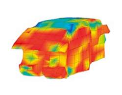
We obtain this way a full vehicle synthesis model allowing
to analyse the contribution of each panel both in terms of
sound power radiated but also in terms of Sound Pressure
Level at various ear points in the interior cavity. Moreover,
it is then possible to «project» these SPL contributions on
the panels (detailed or
averaged) and get an original and powerful 3D
representation of what the driver (or the rear right
passenger in our case) actually hears (cf. figure 8)…
Acoustic Package Optimization
The acoustic package optimization phase aims at
determining the barycenter of the acoustic concepts
-balancing insulation and absorption- that better fits the
target defined in terms of acoustic, weight and price (cf.
section 2). This optimization procedure relies on the poro-
elastic simulation of the acoustic package using simple
transfer matrix codes like [8,9] or SEA models or even
relies on measurements in coupled reverberating rooms
for example, which is the case for the cockpit area here.
The resulting Transmission Loss and diffuse field absorption
coefficient or impedance are introduced as a modification
of the power injected in the passenger compartment (as
∆
TL) and as a modification of the cavity transfer functions
according to the modification of the absorption properties
in the Ray-Tracing model [1]. The resulting optimized SPL
is then calculated at various ear points and compared to
the target.
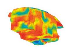
An improvement of this optimization procedure has been
introduced in this study by computing all poro-elastic data
following the thickness cartographies of the insulators
(instead of local average values), leading to a much more
precise simulation (cf. figure 9)
We will now analyse the quality of the poro-elastic simulation
tools, we are using in the optimization phase, compared to
measurements.
Fig. 8 : SPL recomposition 3D ma pat 1 000 Hz, 4th gear 100 km/h ; driver’s position
Fig. 9 : Tunnel insulator thickness cartography example
Vehicle Acoustic Synthesis Method 2nd Generation: an effective hybrid simulation tool to implement acoustic lightweight strategies