Version HTML de base


6
Journée SFA / Renault / SNCF
Acoustique
&
Techniques n° 44
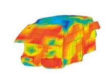
Figure 3 shows an example of radiated sound power 3D
map at 1 000 Hz, 4th gear 100 km/h.
Transfer Functions Measurements
The transfer functions have been measured using the
reciprocity principle by positioning a constant volume
velocity source at two receiver points: Driver’s ear position
and Rear right passenger’s ear position. The reciprocity
relation is given by equation 2 :
€
p
r
2
Q
i
2
⎡
⎣
⎢
⎤
⎦
⎥ =
p
i
' 2
Q
r
' 2
⎡
⎣
⎢
⎤
⎦
⎥
(2)
Due to the point to point intensity measurement technique,
transfer functions are not averaged any more compared
to [1]. The discretization is homogeneous indeed in the
new protocol between sound power and transfer function
measurements and is actually quite refined.
Remark : as we are working with power, it would not make
much difference to consider energetic transfer functions
€
p
i
' 2
W
r
'
, nevertheless it would be then compulsory to
determine the injected power of the monopole source in
the interior cavity which can be measured with a two or
three microphones «intensity like» measurement technique
or with what we are currently testing with a p-
u
probe in
the source nozzle.
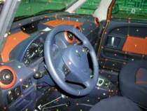
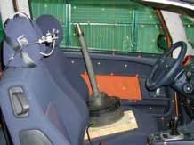
Figure 4 shows the measurement conditions and how the
constant volume velocity source is positioned.
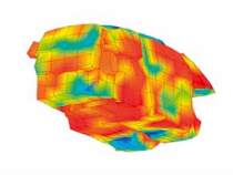
Figure 5 shows an example of a transfer function 3D map
not normalized to the mean squared volume velocity
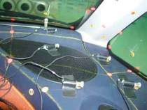
Fig. 2 : Sound power measurement protocol
Fig. 3 : Sound power measurement 3D map at 1 000 Hz, 4th gear 100 km/h
Fig. 4 : Transfer function measurement protocol
Vehicle Acoustic Synthesis Method 2nd Generation: an effective hybrid simulation tool to implement acoustic lightweight strategies